Post by HeadHunter on Dec 4, 2021 16:08:34 GMT
The venerable KWC 1911 has been around in many different guises for a considerable amount of time, okay no where near as long as the real steel 1911 has but in the world of CO2 replicas it's one of the Grandfathers of the hobby. A hugely popular pistol amongst replica collectors, so much so that most of us have at least one if not two (or three) proudly held in our collections. With this in mind, I thought that it was about time that someone wrote a full strip down guide to help any interested members out when it comes to the KWC 1911.
Contents
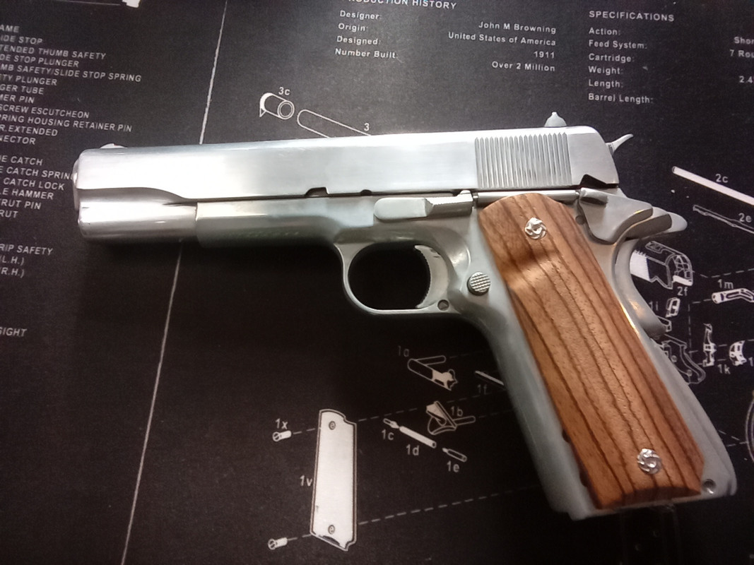
Above - Although it's not your standard Remington RAC 1911, it's still just a KWC 1911.
NOTE - For the purpose of this guide I've used my modified Remington 1911 RAC (see above picture), it may externally look very different to yours but I can assure you that it is just a plain old KWC 1911 underneath that exterior. There are so many different types of 1911s made by KWC that to cover all the variations would too time consuming and make this guide even more confusing to read. There are a few different types of hammer, sights, beavertails, mainspring housings, triggers and even differences in frames (under barrel tactical rails etc.) but essentially they are all the same beast on the inside, everything connects in the same way, in the same place irrespective of these slight variations to some of the parts, so just because yours doesn't look identical to mine is no cause for concern, they all work in exactly the same way.
Full strip down - Slide
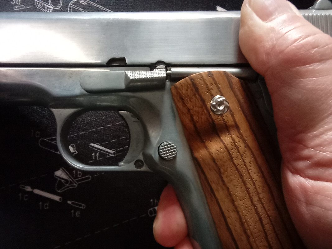
Firstly before doing anything you need to remove the magazine from the gun, then we need to remove the slide, this can be done by moving the slide rearward and line up the slide release/takedown lever up to the appropriate notch as seen in the picture below.
Now just pull the slide release arm completely away from the body and then move the slide forward until it comes off the rails on the frame, you should end up with the same as the picture below.
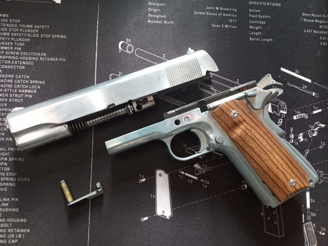
Next, take the slide and turn it upside down. You should see the recoil spring where it attaches to the lower section of the barrel assembly.
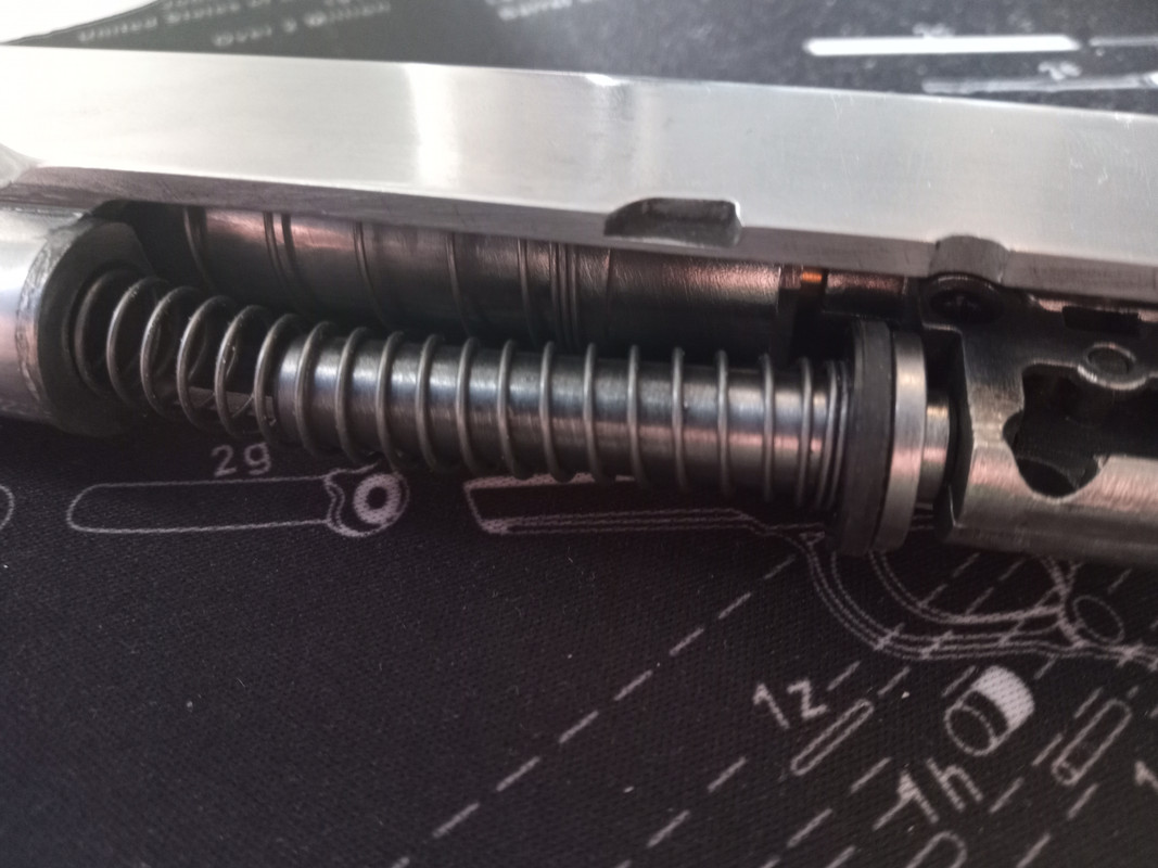
Carefully unhook the spring (along with the guide pin) away from the connecting point and remove the whole assembly from the gun. You should have three main pieces; the recoil spring, the recoil spring guide and the recoil spring plug as in the picture below.
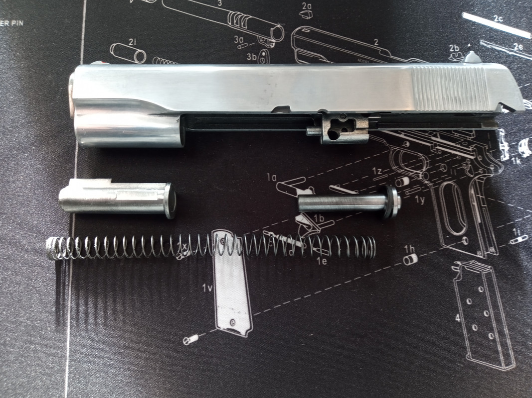
At the muzzle end of the slide there is the barrel nut, this needs to be moved anti clockwise by approximately 45 degrees, that will unlock it and it should pop out gently under the force of the barrel spring. The barrel spring needs to be removed next and then the barrel assembly can be slid out the front as well.
IMPORTANT NOTE: The barrel spring has a slight gradual taper to it, the narrowest end ALWAYS sits against the barrel assembly and the widest end sits against the barrel nut.
You should end up with the three sections as in the picture below.
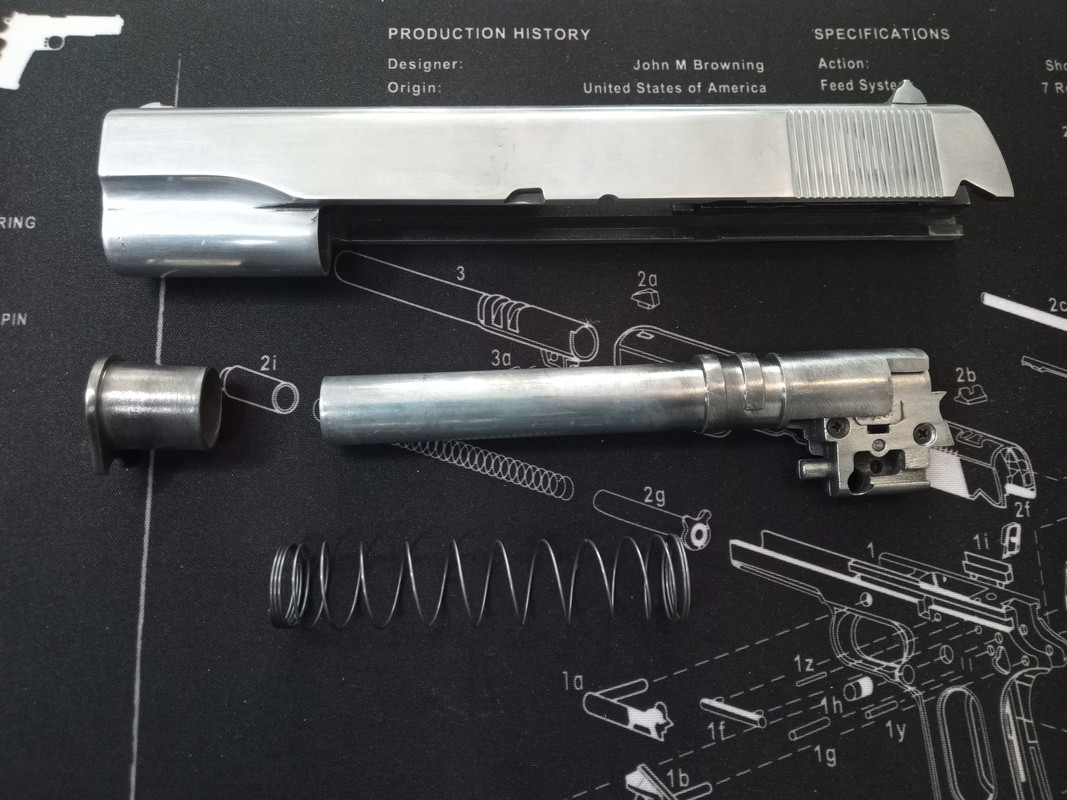
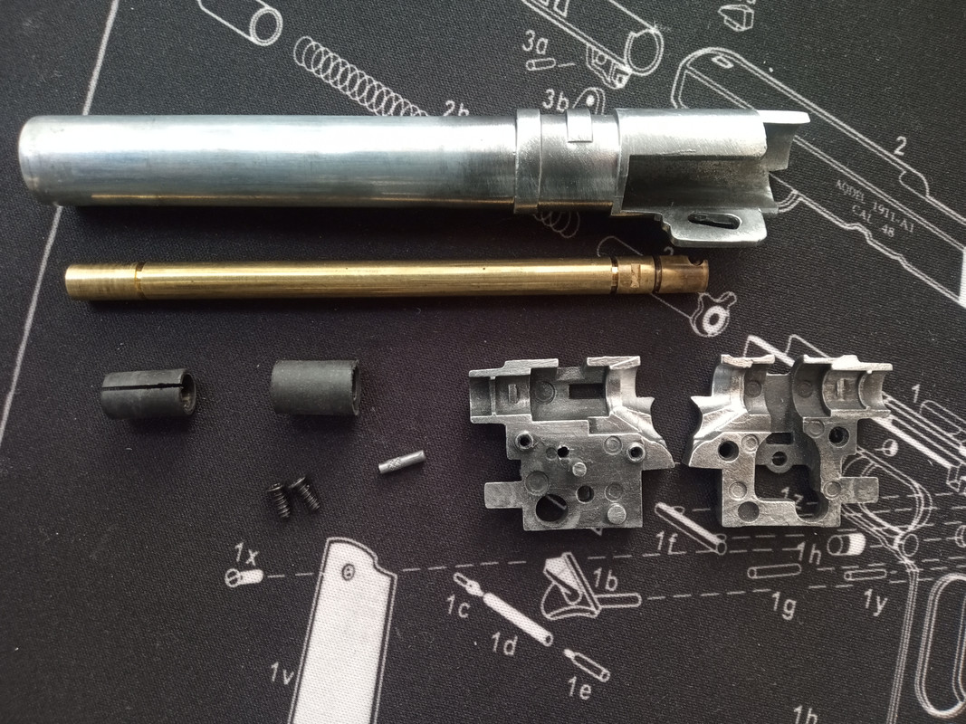
To strip the barrel assembly down you need to use a hammer and a small drift and gently tap out the cam pin (which is labelled with a red arrow in the picture below).

Then remove the two screws from the inner barrel and breech assembly and you should have the inner barrel, breech assembly (in two parts), a soft rubber boot (for the breech end), a hard plastic shim (for the muzzle end), the cam pin, the barrel shroud and the two screws.
Now we need to remove the main valve from the slide.
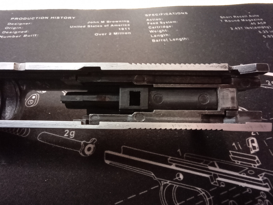
Using a suitably sized allen key undo the the stud that sits underneath where the hammer would rest, once removed the valve unit can be lifted straight out.
NOTE - There is a long thin spring with a small stud (marked with the red arrow) that is likely to shoot out as you remove the valve assembly, if unfamiliar with doing this it's best to do this inside a bag, saving you the inconvenience of scrambling around on all fours looking for errant gun parts.
You should end up looking like the picture below.

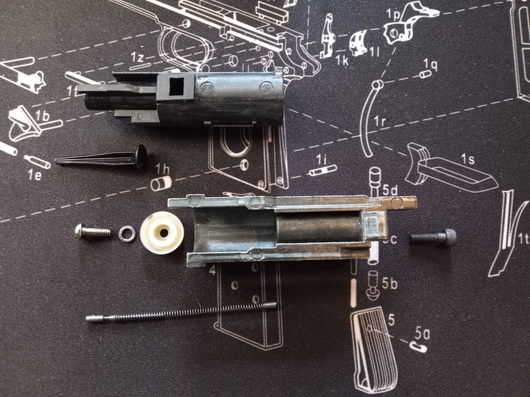
To disassemble the valve assembly you need to pull the nozzle forward and it will become free of the rest of the unit, there is a small part called the 'rocket nozzle' that sits inside of the nozzle, just tipping it up will allow it to fall straight out. then unscrew the seal from the assembly. It should all look like the picture below once disassembled.
If you look inside the slide you'll notice two more screws,
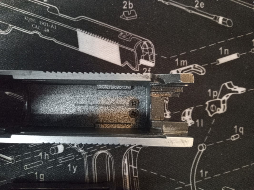
Unscrew these and that will allow the rear sight to be removed.
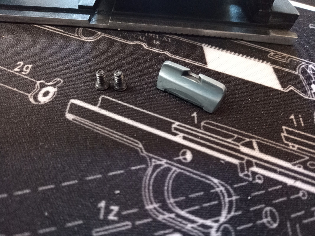
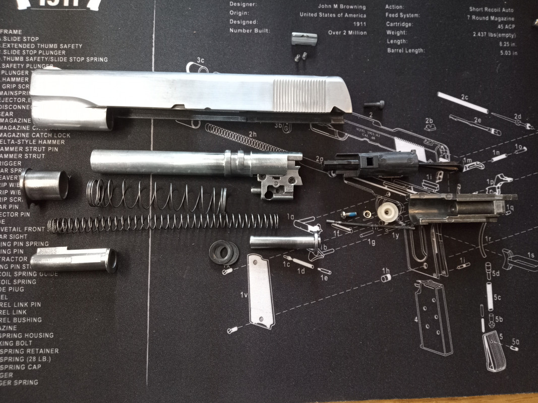
Now that's all the slide's components removed and completely disassembled.
Full strip down - Frame
So to start, firstly remove the grips.
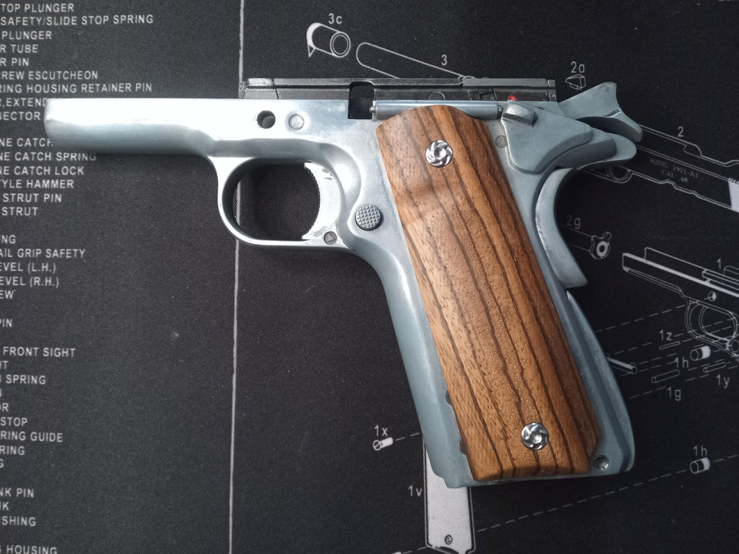
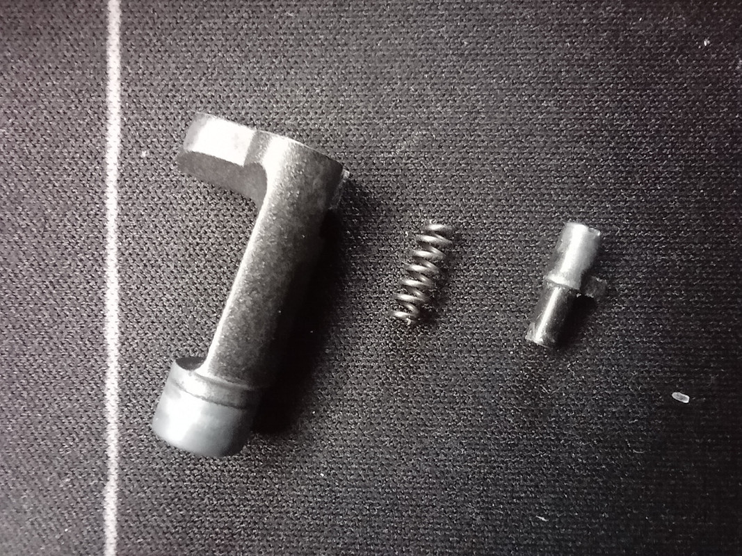
Then remove the magazine release button, this can be done from the right hand side by using a very small flat head screwdriver and pushing the screw down and then turning about 70 degrees anticlockwise.

Once it's removed it breaks down into three component parts.
Next, we need to release the pressure off of the lock work by removing the mainspring housing. This can be a little tricky as you need to force against the main spring housing to release the retaining pin at the bottom of the grip. If you get the pressure just right the retaining pin will fall out under it's own weight otherwise you'll just need to poke it through.
The diagram below shows where to push and direction of the force need (the green arrow) and it also highlights the retaining pin's position (the red arrow).

Once removed, you should have the mainspring housing and the retaining pin.
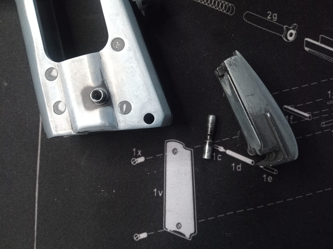
This can be further broken down into four further parts; the housing, the mainspring, the mainspring guide and the bolt.


Next we need to remove the front lock work screw,

And lift out the safety switch (which can only be done if the hammer is fully cocked),

Once you've removed the safety switch the grip safety and three fingered spring will also come out with it.

now the safety has been removed, the dual ended spring tensioner for the slide release and safety switch can be removed from it's holder, it can only be slid out from the rear end of the holder. You can now gain access to the hammer pin screw,

Unscrew the screw halfway and gently push it down, this will 'pop' the other end of the hammer pin proud of the frame on the right hand side,

Once you've removed the screw and the pin fully from the frame you'll notice that the pin has two flat sides (top & bottom) to key it back into position.

Now you're ready to start lifting out the complete lock work section in one piece, carefully lift it vertically from the frame,

Now it's removed you should have something that looks like this,

To strip this any further you need to lift off the internal hammer section,

And then lift the hammer out,

NB. The 'Rat Tail' is held in place on the hammer by a small roll pin, if needed it can be removed by using a small drift.
Then lift the trigger sear out,

and finally the disconnect bar,
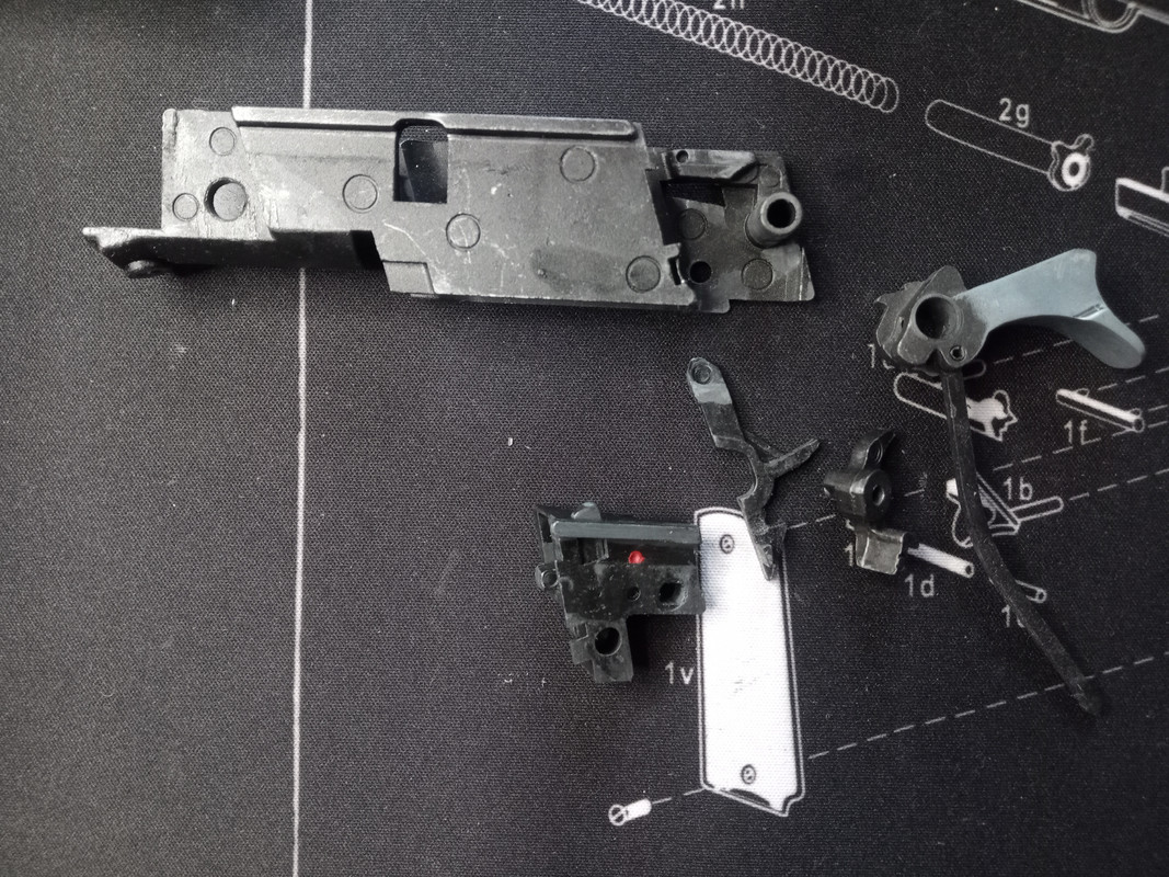
turning our attention back to the internal hammer, you need to depress the disconnector (red arrow in picture),

This will allow the hammer to fall back and take some of the 'weight' out of the spring for further disassembly,

Now carefully unhook the lower leg of the spring and remove the spring and the hammer,

You've now got access to the screw for the plate that holds the disconnector and the spring in place, remove the screw and then carefully remove the covering plate,

Now you can remove the disconnector and it's compression spring, below are all the parts for the internal hammer system,

The last bit of the frame to be disassembled is the trigger and the trigger return spring,

WARNING - the spring is likely to 'ping' off when you try to remove it (and fixing back into place is no easy feat either), I find it's best to keep your finger on it as you remove it to stop it from flying off or do the whole process inside a plastic bag.
Once the spring is removed the trigger will just slide out rearwards,

There is a small drift pin that can be punched out that will allow you to remove the actual trigger from the trigger stirrup.
Full strip down - Magazine
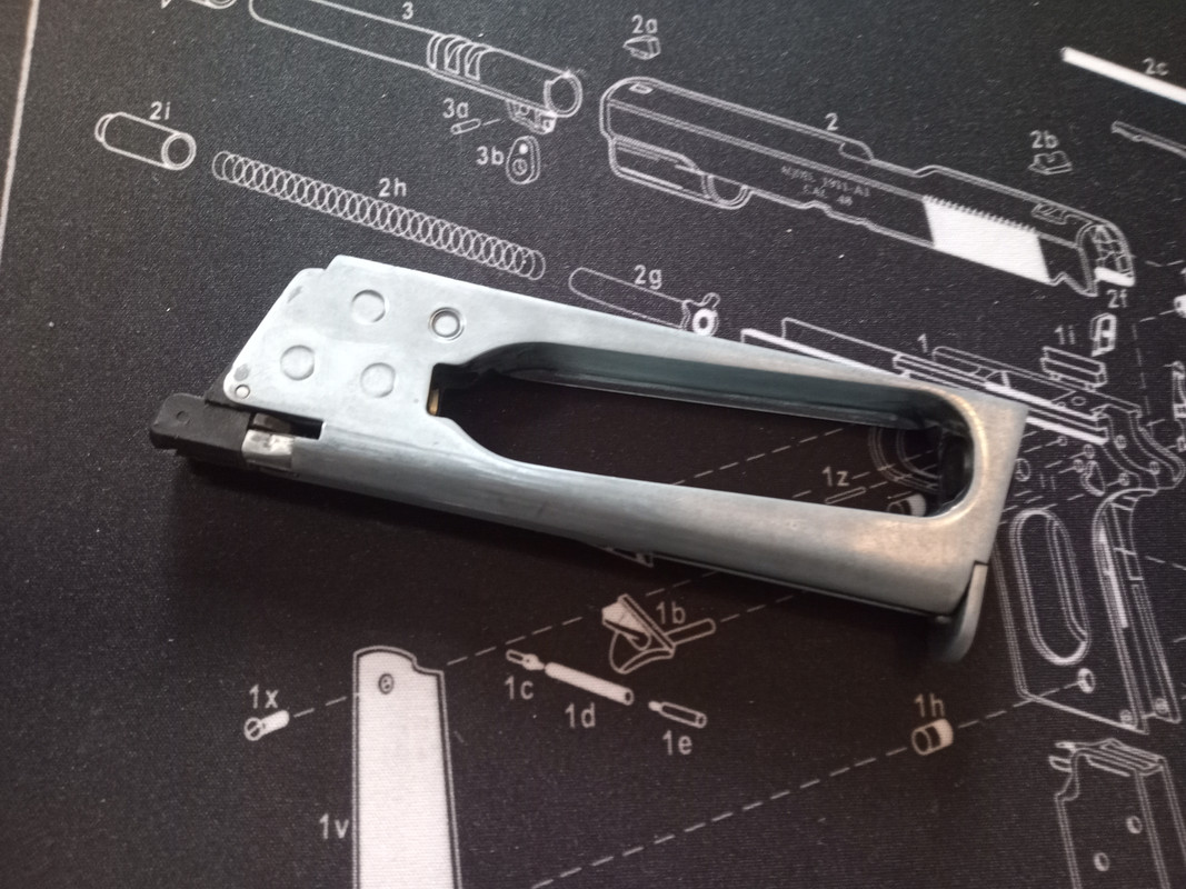
Starting at the bottom of the magazine you'll see two screws.
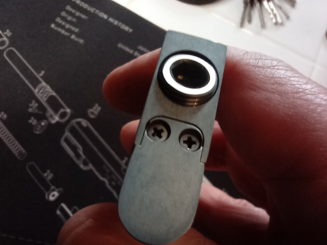
Remove these screws and the retaining plate, magazine follower and magazine spring can be removed.
NOTE - The magazine spring's narrower end sits against the magazine follower and the wider end sits against the retaining plate.
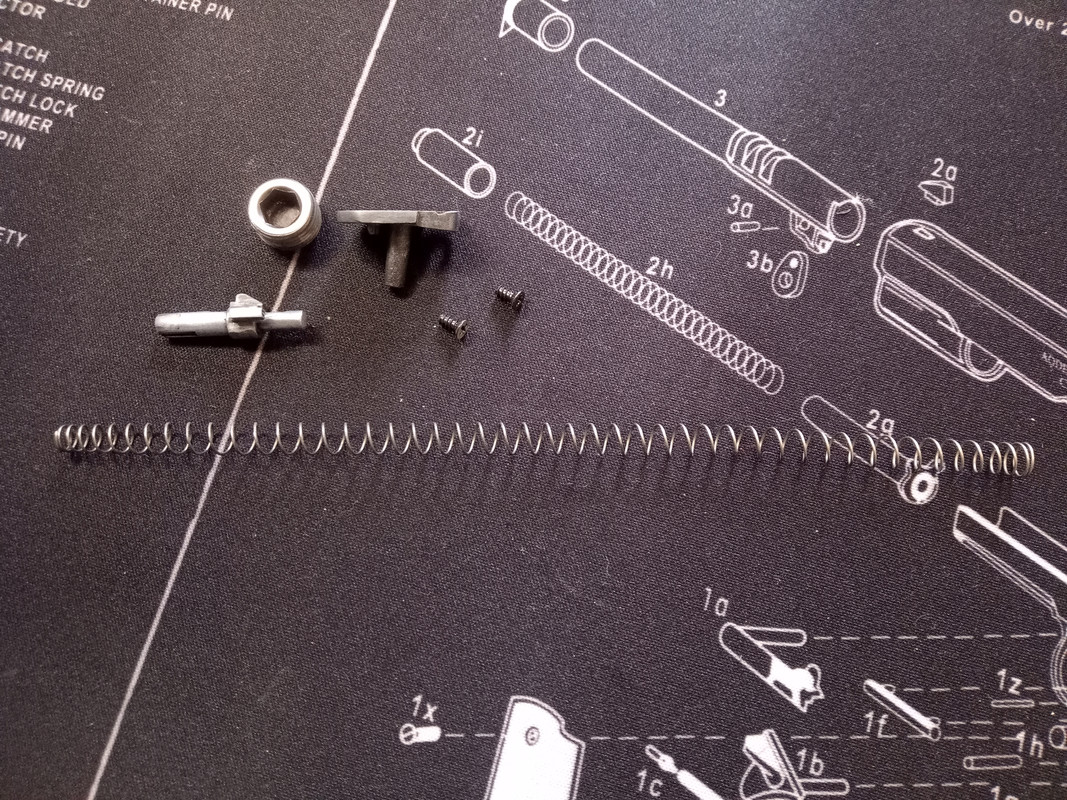
Next, moving on to the valve,
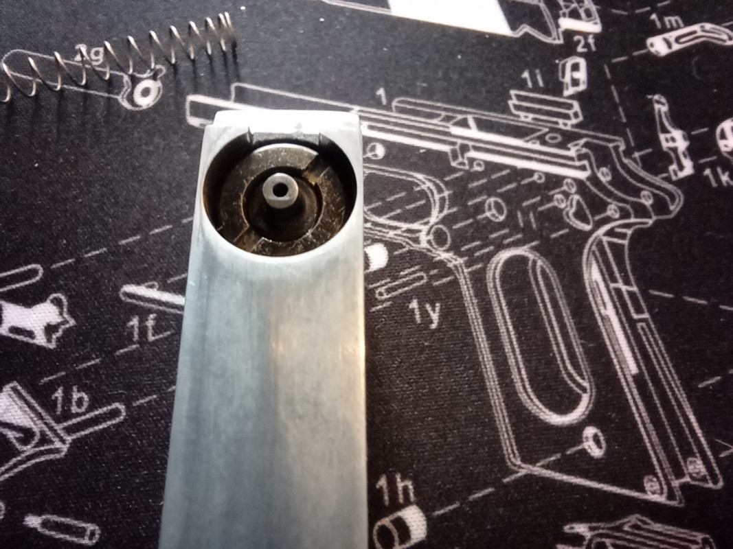
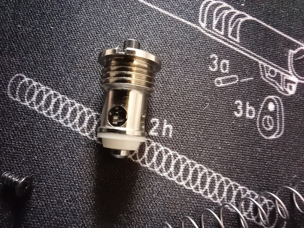
Using a valve removal tool (or a modified large flat headed screw driver) unscrew the valve from the magazine. There is a very small O-ring that sits inside the magazine that seals the valve against the body of the magazine, it will either fall out out when the valve is removed or remain inside but just be aware of it.
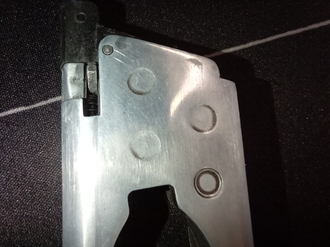
To remove the feed lips and the transfer port you need to use a hammer and a small drift to punch out the retaining pin from the top of the magazine from the left hand side.
Once removed you should have the items in the picture below.
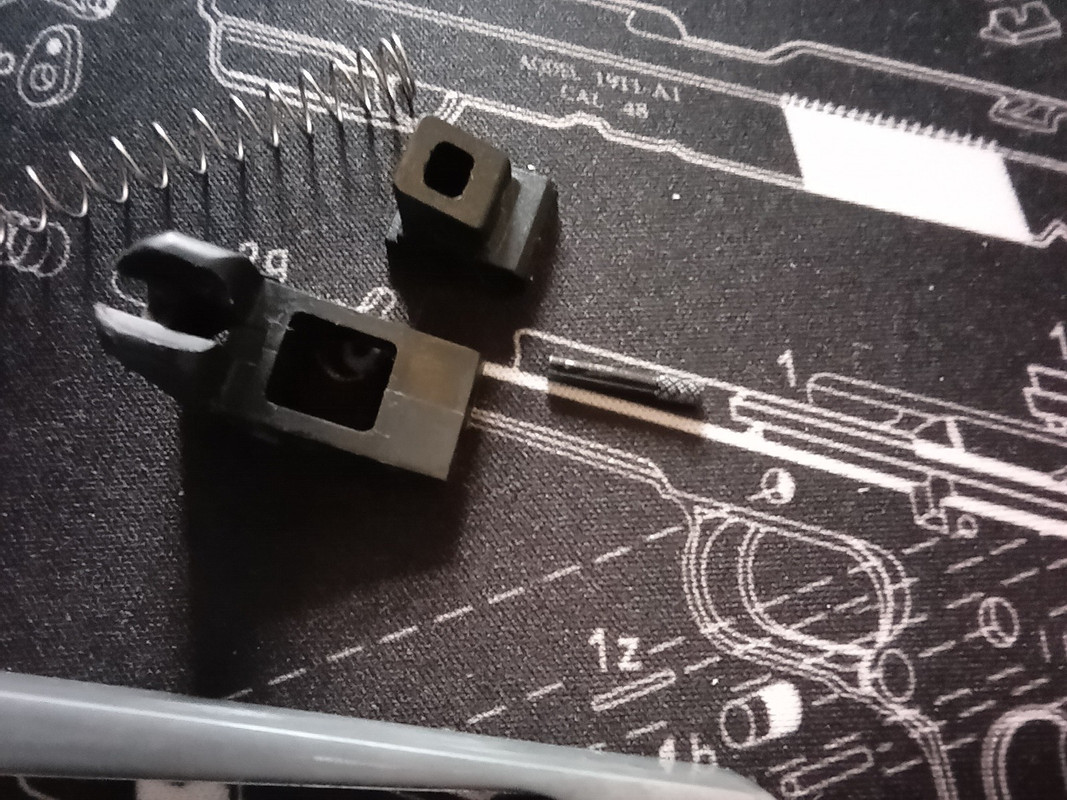
Now you have most of the components that go to make up the magazine, apart from the CO2 piercing nozzle and seal. Removing these is not advised unless you are going to replace the seal or the piercing plate as they can be a problem to 'set' right again and it should only ever be done as a final option prior to replacement.

Full strip down - Notes for re-assembly
Be very careful not to over tighten any screws too much as you'll strip the threads in the die cast frame, remember it's better to do them finger tight rather than hand tight.
If you're re-assembling the gun with a view to leaving it together for any length of time, a very small dot of thread locker on the screws will be needed to keep it all from loosening up.
Clean parts as you disassemble and lubricate parts as you re-assemble.
When fitting the trigger return spring I've found that it's best to fit the rear end of it against the frame and manipulate it into position using the flat of your index finger, that way it stops it from shooting off and getting lost.
The hammer bar is keyed, so the flats need to go top and bottom for it to go back in properly.
When refitting the main valve back into the slide the long spring and stud have to be depressed back into the housing to allow it to fit back into the slide correctly, a small flat screwdriver is very handy for this.
The two screws that hold the inner barrel and breech assembly together will DEFINITELY need to be threadlocked when re-assembling.
The recoil spring guide has two washers, the rubber one goes on first, then the thin metal one is next and finally the spring goes on. The rubber washer acts as a cushion and will only function correctly if it's between the end of the guide and the metal washer.
Aside from when you have to compress a spring there are no parts that need to be 'forced' into their correct positions, if you find that you are having to force something then check that there isn't something that you've missed in the re-assembly of the gun.
When re-assembling the frame, keep the hammer in the fully cocked position as otherwise the safety switch will not seat properly back into the frame, also whilst placing the safety switch back into it's position you need to compress the tensioning spring to allow the safety to go all the way back fully, again a small flat headed screwdriver is perfect for the job.
When refitting the cam pin, you'll notice that it has knurling nearer to one end than the other. When punching it back into place (from the right hand side) the knurling needs to be nearer to you (the smoother end is going into the barrel assembly). Make sure that you seat it all the way in, that way the knurling engages fully with the seating hole and the pin should then be flush with the cut out of the cam that it operates.
Remember that the barrel spring has a narrow and a wide end, the narrow end goes into the gun and against the barrel assembly whereas the wider end goes towards the muzzle (against the barrel nut).
The three fingered leaf spring can be awkward to refit sometimes, it's one of those parts that becomes far easier the more times you do it, just take your time, fit the spring, lay the hammer's rat tail over the top (keeping it central) and then put the grip safety over the top of it all (the rat tail will fall into the central divot on the rear of the grip safety). It's easy enough to hold the grip safety in place whilst you seat the safety switch into it's proper position.
It's always handy to take photographs of any gun when disassembling, I haven't taken multiple pictures from various angles during this strip down, you may find it handy to have these extra pictures to aid you in re-assembling the gun.
If you've used a thread locker on the reassembly then remember that it needs to fully cure before you use the gun again, otherwise you'll loosen the screws and they'll cure in a loose position which defeats the whole purpose of using a thread locker in the first place.
Take your time, a good job is never done quickly but bad ones always are.
Contents
- Slide
- Frame
- Magazine
- Notes for re-assembly

Above - Although it's not your standard Remington RAC 1911, it's still just a KWC 1911.
NOTE - For the purpose of this guide I've used my modified Remington 1911 RAC (see above picture), it may externally look very different to yours but I can assure you that it is just a plain old KWC 1911 underneath that exterior. There are so many different types of 1911s made by KWC that to cover all the variations would too time consuming and make this guide even more confusing to read. There are a few different types of hammer, sights, beavertails, mainspring housings, triggers and even differences in frames (under barrel tactical rails etc.) but essentially they are all the same beast on the inside, everything connects in the same way, in the same place irrespective of these slight variations to some of the parts, so just because yours doesn't look identical to mine is no cause for concern, they all work in exactly the same way.
Full strip down - Slide
Firstly before doing anything you need to remove the magazine from the gun, then we need to remove the slide, this can be done by moving the slide rearward and line up the slide release/takedown lever up to the appropriate notch as seen in the picture below.

Now just pull the slide release arm completely away from the body and then move the slide forward until it comes off the rails on the frame, you should end up with the same as the picture below.

Next, take the slide and turn it upside down. You should see the recoil spring where it attaches to the lower section of the barrel assembly.

Carefully unhook the spring (along with the guide pin) away from the connecting point and remove the whole assembly from the gun. You should have three main pieces; the recoil spring, the recoil spring guide and the recoil spring plug as in the picture below.

At the muzzle end of the slide there is the barrel nut, this needs to be moved anti clockwise by approximately 45 degrees, that will unlock it and it should pop out gently under the force of the barrel spring. The barrel spring needs to be removed next and then the barrel assembly can be slid out the front as well.
IMPORTANT NOTE: The barrel spring has a slight gradual taper to it, the narrowest end ALWAYS sits against the barrel assembly and the widest end sits against the barrel nut.
You should end up with the three sections as in the picture below.

To strip the barrel assembly down you need to use a hammer and a small drift and gently tap out the cam pin (which is labelled with a red arrow in the picture below).

Then remove the two screws from the inner barrel and breech assembly and you should have the inner barrel, breech assembly (in two parts), a soft rubber boot (for the breech end), a hard plastic shim (for the muzzle end), the cam pin, the barrel shroud and the two screws.

Now we need to remove the main valve from the slide.

Using a suitably sized allen key undo the the stud that sits underneath where the hammer would rest, once removed the valve unit can be lifted straight out.
NOTE - There is a long thin spring with a small stud (marked with the red arrow) that is likely to shoot out as you remove the valve assembly, if unfamiliar with doing this it's best to do this inside a bag, saving you the inconvenience of scrambling around on all fours looking for errant gun parts.
You should end up looking like the picture below.

To disassemble the valve assembly you need to pull the nozzle forward and it will become free of the rest of the unit, there is a small part called the 'rocket nozzle' that sits inside of the nozzle, just tipping it up will allow it to fall straight out. then unscrew the seal from the assembly. It should all look like the picture below once disassembled.

If you look inside the slide you'll notice two more screws,

Unscrew these and that will allow the rear sight to be removed.

Now that's all the slide's components removed and completely disassembled.

Full strip down - Frame
So to start, firstly remove the grips.

Then remove the magazine release button, this can be done from the right hand side by using a very small flat head screwdriver and pushing the screw down and then turning about 70 degrees anticlockwise.

Once it's removed it breaks down into three component parts.

Next, we need to release the pressure off of the lock work by removing the mainspring housing. This can be a little tricky as you need to force against the main spring housing to release the retaining pin at the bottom of the grip. If you get the pressure just right the retaining pin will fall out under it's own weight otherwise you'll just need to poke it through.
The diagram below shows where to push and direction of the force need (the green arrow) and it also highlights the retaining pin's position (the red arrow).

Once removed, you should have the mainspring housing and the retaining pin.

This can be further broken down into four further parts; the housing, the mainspring, the mainspring guide and the bolt.


Next we need to remove the front lock work screw,

And lift out the safety switch (which can only be done if the hammer is fully cocked),

Once you've removed the safety switch the grip safety and three fingered spring will also come out with it.

now the safety has been removed, the dual ended spring tensioner for the slide release and safety switch can be removed from it's holder, it can only be slid out from the rear end of the holder. You can now gain access to the hammer pin screw,

Unscrew the screw halfway and gently push it down, this will 'pop' the other end of the hammer pin proud of the frame on the right hand side,

Once you've removed the screw and the pin fully from the frame you'll notice that the pin has two flat sides (top & bottom) to key it back into position.

Now you're ready to start lifting out the complete lock work section in one piece, carefully lift it vertically from the frame,

Now it's removed you should have something that looks like this,

To strip this any further you need to lift off the internal hammer section,

And then lift the hammer out,

NB. The 'Rat Tail' is held in place on the hammer by a small roll pin, if needed it can be removed by using a small drift.
Then lift the trigger sear out,

and finally the disconnect bar,

turning our attention back to the internal hammer, you need to depress the disconnector (red arrow in picture),

This will allow the hammer to fall back and take some of the 'weight' out of the spring for further disassembly,

Now carefully unhook the lower leg of the spring and remove the spring and the hammer,

You've now got access to the screw for the plate that holds the disconnector and the spring in place, remove the screw and then carefully remove the covering plate,

Now you can remove the disconnector and it's compression spring, below are all the parts for the internal hammer system,

The last bit of the frame to be disassembled is the trigger and the trigger return spring,

WARNING - the spring is likely to 'ping' off when you try to remove it (and fixing back into place is no easy feat either), I find it's best to keep your finger on it as you remove it to stop it from flying off or do the whole process inside a plastic bag.
Once the spring is removed the trigger will just slide out rearwards,

There is a small drift pin that can be punched out that will allow you to remove the actual trigger from the trigger stirrup.
Full strip down - Magazine

Starting at the bottom of the magazine you'll see two screws.

Remove these screws and the retaining plate, magazine follower and magazine spring can be removed.
NOTE - The magazine spring's narrower end sits against the magazine follower and the wider end sits against the retaining plate.

Next, moving on to the valve,

Using a valve removal tool (or a modified large flat headed screw driver) unscrew the valve from the magazine. There is a very small O-ring that sits inside the magazine that seals the valve against the body of the magazine, it will either fall out out when the valve is removed or remain inside but just be aware of it.

To remove the feed lips and the transfer port you need to use a hammer and a small drift to punch out the retaining pin from the top of the magazine from the left hand side.

Once removed you should have the items in the picture below.

Now you have most of the components that go to make up the magazine, apart from the CO2 piercing nozzle and seal. Removing these is not advised unless you are going to replace the seal or the piercing plate as they can be a problem to 'set' right again and it should only ever be done as a final option prior to replacement.

Full strip down - Notes for re-assembly
Be very careful not to over tighten any screws too much as you'll strip the threads in the die cast frame, remember it's better to do them finger tight rather than hand tight.
If you're re-assembling the gun with a view to leaving it together for any length of time, a very small dot of thread locker on the screws will be needed to keep it all from loosening up.
Clean parts as you disassemble and lubricate parts as you re-assemble.
When fitting the trigger return spring I've found that it's best to fit the rear end of it against the frame and manipulate it into position using the flat of your index finger, that way it stops it from shooting off and getting lost.
The hammer bar is keyed, so the flats need to go top and bottom for it to go back in properly.
When refitting the main valve back into the slide the long spring and stud have to be depressed back into the housing to allow it to fit back into the slide correctly, a small flat screwdriver is very handy for this.
The two screws that hold the inner barrel and breech assembly together will DEFINITELY need to be threadlocked when re-assembling.
The recoil spring guide has two washers, the rubber one goes on first, then the thin metal one is next and finally the spring goes on. The rubber washer acts as a cushion and will only function correctly if it's between the end of the guide and the metal washer.
Aside from when you have to compress a spring there are no parts that need to be 'forced' into their correct positions, if you find that you are having to force something then check that there isn't something that you've missed in the re-assembly of the gun.
When re-assembling the frame, keep the hammer in the fully cocked position as otherwise the safety switch will not seat properly back into the frame, also whilst placing the safety switch back into it's position you need to compress the tensioning spring to allow the safety to go all the way back fully, again a small flat headed screwdriver is perfect for the job.
When refitting the cam pin, you'll notice that it has knurling nearer to one end than the other. When punching it back into place (from the right hand side) the knurling needs to be nearer to you (the smoother end is going into the barrel assembly). Make sure that you seat it all the way in, that way the knurling engages fully with the seating hole and the pin should then be flush with the cut out of the cam that it operates.
Remember that the barrel spring has a narrow and a wide end, the narrow end goes into the gun and against the barrel assembly whereas the wider end goes towards the muzzle (against the barrel nut).
The three fingered leaf spring can be awkward to refit sometimes, it's one of those parts that becomes far easier the more times you do it, just take your time, fit the spring, lay the hammer's rat tail over the top (keeping it central) and then put the grip safety over the top of it all (the rat tail will fall into the central divot on the rear of the grip safety). It's easy enough to hold the grip safety in place whilst you seat the safety switch into it's proper position.
It's always handy to take photographs of any gun when disassembling, I haven't taken multiple pictures from various angles during this strip down, you may find it handy to have these extra pictures to aid you in re-assembling the gun.
If you've used a thread locker on the reassembly then remember that it needs to fully cure before you use the gun again, otherwise you'll loosen the screws and they'll cure in a loose position which defeats the whole purpose of using a thread locker in the first place.
Take your time, a good job is never done quickly but bad ones always are.


